Guide wire power poles are crucial infrastructure, supporting vital utilities. Their reliable operation depends on careful construction and consistent maintenance, ensuring safety and longevity.
1.1 What is a Guide Wire Power Pole?
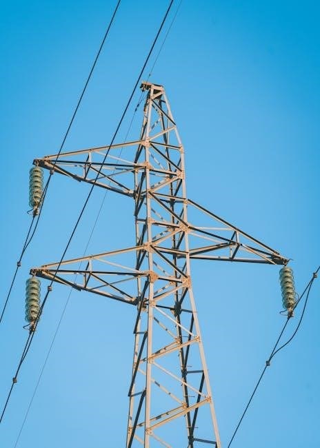
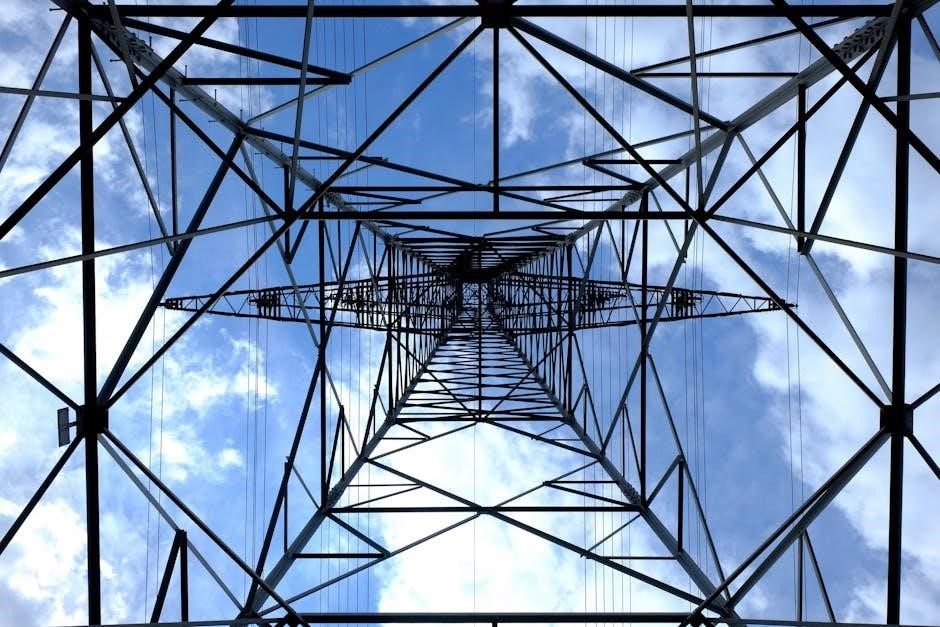
Guide wire power poles represent a specific type of utility pole, distinguished by the implementation of guy wires for enhanced stability. These poles aren’t self-supporting; instead, they rely on tensioned cables – the guy wires – anchored to the ground to counteract bending moments caused by wind, ice, or the weight of carried equipment.
Typically utilized for taller poles or those supporting heavier loads, these systems offer a cost-effective solution compared to larger, more robust self-supporting structures. They are commonly found supporting overhead power lines, communication cables, and lighting fixtures. The integrity of the entire system—pole, wires, and anchors—is paramount for safe and reliable operation, demanding regular inspection and maintenance.
1.2 Importance of Proper Installation and Maintenance
Proper installation of guide wire power poles is fundamental to public safety and service reliability. Incorrect tensioning, inadequate anchoring, or improper grounding can lead to pole failure, resulting in power outages, communication disruptions, and potentially hazardous situations. Initial construction must adhere strictly to engineering specifications and industry best practices.
Consistent maintenance is equally critical. Regular inspections should identify corrosion, damaged wires, loose anchors, or any signs of structural weakness. Proactive corrosion prevention and timely repairs extend the pole’s lifespan and prevent catastrophic failures. Neglecting maintenance compromises the structural integrity, increasing the risk of accidents and escalating long-term costs.
Components of a Guide Wire Power Pole System
A typical system includes the pole itself, guy wires for stability, robust anchors, and crucial insulators—all working together to ensure safe, reliable power delivery.
2.1 The Power Pole Itself: Materials and Construction
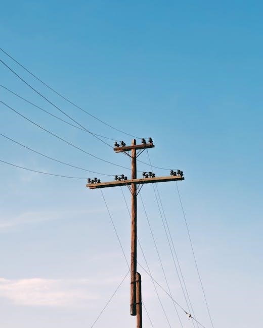
Power poles are primarily constructed from wood, concrete, or steel. Wooden poles, often treated with preservatives, remain common due to cost-effectiveness and flexibility. Concrete poles offer greater strength and longevity, resisting decay and requiring less maintenance, making them suitable for harsh environments. Steel poles, while more expensive, provide exceptional strength-to-weight ratios and are often used in areas prone to high winds or heavy ice loads.
Construction involves careful selection of materials based on anticipated loads and environmental factors. Poles must withstand the weight of conductors, insulators, and hardware, as well as wind and ice loads. Proper pole treatment and construction techniques are vital for ensuring structural integrity and extending the service life of the pole, contributing to overall system reliability.
2.2 Guy Wires: Types and Specifications
Guy wires are critical components, providing stability to power poles. They are typically constructed from galvanized steel strand, offering high tensile strength and corrosion resistance. Different wire gauges and constructions are selected based on pole height, load requirements, and environmental conditions. Common types include standard strand, and specialized coated strands for enhanced durability.
Specifications dictate minimum breaking strength, allowable tension, and corrosion protection standards. Proper selection ensures the guy wire can support the pole’s weight and withstand extreme wind loads. Regular inspection is crucial, as damaged or corroded guy wires compromise pole stability. Maintaining correct tension is also vital for optimal performance and preventing premature failure.
2.3 Anchors: Design and Installation
Anchors are fundamental to guy wire system integrity, securely transferring tension to the ground. Designs vary based on soil conditions, including deadman anchors buried in trenches, and rock anchors drilled into bedrock. Proper installation is paramount; anchors must be buried at the correct depth and angle, and backfill compacted adequately to achieve specified holding capacity;
Installation procedures require careful consideration of surrounding utilities to prevent damage. Anchor rods must be galvanized to resist corrosion, and connections to guy wires should be regularly inspected for tightness. Detailed drawings and engineering specifications dictate anchor placement and size, ensuring sufficient resistance to overturning moments. A detail of guard installation on a guy wire is illustrated in Figure 15.
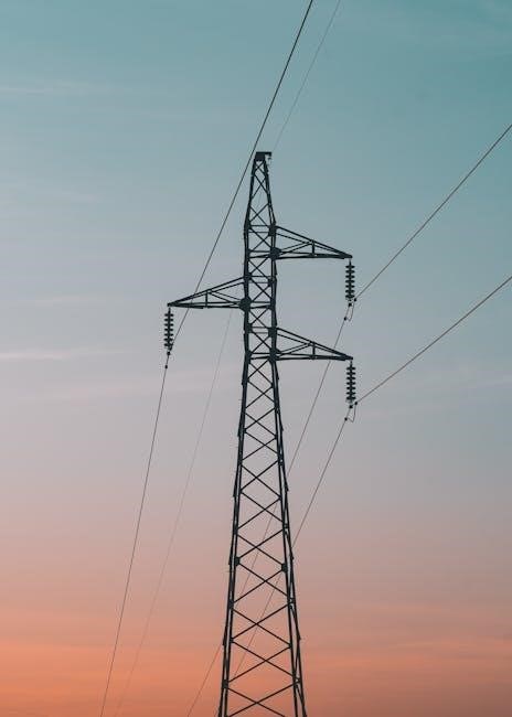
2.4 Insulators: Role in Electrical Safety
Insulators are critical components, preventing unwanted electrical conduction from energized power lines to the grounded pole structure and, crucially, the guy wires. They maintain electrical isolation, safeguarding personnel and equipment. Constructed from materials like porcelain or polymer, insulators must withstand significant voltage stress and environmental factors like weather and pollution.
Proper installation ensures a secure mechanical connection while preserving electrical integrity. The system neutral and pole ground are bonded below the insulator, enhancing safety. Regular inspection for cracks, contamination, or damage is vital. Grounding the guy wire below the insulator is a key safety measure, diverting fault currents to ground and minimizing risk. Maintaining adequate ground resistance is paramount for effective protection.
Construction Specifications for Pole Top Assemblies
Pole top assemblies require careful hardware model selection and a structured assessment process. Grounding guy wires to the system neutral is essential for safety.
3.1 Hardware Model Considerations
Selecting the appropriate hardware models for pole top assemblies is paramount for structural integrity and long-term reliability. Considerations must encompass the anticipated load, environmental factors – including wind and ice – and compatibility with existing pole infrastructure. Different guy wire configurations necessitate varying hardware specifications; for instance, strain insulators and turnbuckles must be rated to handle the maximum tension expected in the system.
Furthermore, material selection plays a critical role. Galvanized steel is commonly used for its corrosion resistance, but stainless steel may be preferred in harsh environments. Detailed engineering calculations should validate hardware choices, ensuring they meet or exceed relevant industry standards. Proper documentation of hardware models used during construction is vital for future maintenance and inspection purposes, facilitating efficient component replacement and system upgrades.
3.2 Metrics Structure for Assessment
A robust metrics structure is essential for assessing the performance and safety of guide wire power pole systems. Key metrics include guy wire tension, measured regularly to ensure it remains within acceptable limits, and insulator condition, assessed for cracks or contamination. Visual inspections should document corrosion levels on hardware and poles themselves, categorized by severity.
Structural assessments should quantify pole deflection under load, comparing readings to design specifications. Collected data, including GPU architecture and profiled kernels, aids in predictive maintenance. Regular monitoring of ground resistance, particularly at guy wire anchors, verifies effective grounding. A standardized reporting format, detailing dates, measurements, and corrective actions, ensures consistent data analysis and informed decision-making regarding system maintenance and upgrades.
3;3 Grounding Requirements for Guy Wires
Effective grounding of guy wires is paramount for electrical safety in guide wire power pole systems. Guy wires must be bonded to the system neutral, creating a low-impedance path for fault currents. This connection, installed below the insulator, diverts potentially hazardous electricity to ground. Furthermore, bonding to the pole ground wire, when present, enhances the grounding network’s effectiveness.
Adequate ground resistance is critical; measurements should consistently fall within acceptable limits, typically below a specified threshold. Regular testing and maintenance of grounding connections are essential to prevent corrosion and ensure continuity. Proper grounding minimizes the risk of step and touch potentials, safeguarding personnel and equipment. Detailed documentation of grounding configurations and test results is vital for compliance and safety audits.
Guy Wire Installation Best Practices
Optimal guide wire power pole installation requires precise tensioning, correct departure angles, and careful spacing to avoid interference with existing utilities and ensure stability.
4.1 Proper Tensioning Techniques
Achieving correct tension in guide wire power pole systems is paramount for structural integrity and longevity. Tension must balance supporting the pole’s weight against wind loads, preventing excessive sag or strain. Initial tensioning often utilizes come-alongs or hydraulic tensioners, carefully monitored with tension dynamometers to meet specified engineering requirements.
Uneven tension across guy wires introduces stress concentrations, potentially leading to premature failure. Regularly re-tensioning is crucial, as wires stretch over time. Proper tensioning also minimizes sway, enhancing the stability of the pole and the safety of attached equipment. Consistent monitoring and adjustment, guided by manufacturer specifications and industry best practices, are essential for maintaining optimal performance and preventing costly repairs or replacements.
4.2 Angle of Departure and Spacing
Optimal guide wire power pole performance relies heavily on correct angle of departure and spacing of guy wires. Generally, angles between 30 and 45 degrees from vertical provide the best balance of lateral support and tension efficiency. Wider angles reduce tension, while narrower angles increase it, potentially overstressing anchors.
Spacing between anchor points should be symmetrical to distribute loads evenly. The distance is dictated by pole height and anticipated wind loads, typically ranging from 0.7 to 1.2 times the pole height. Proper spacing prevents interference with other utilities and ensures adequate ground clearance. Careful consideration of these factors minimizes stress on the pole and anchors, maximizing structural integrity and long-term reliability.
4.3 Avoiding Interference with Other Utilities
When installing guide wire power poles, meticulous planning is essential to prevent interference with existing underground or overhead utilities. A thorough site survey, including utility locates, is the first critical step. Guy wire anchor placement must avoid conflicting with gas lines, water pipes, sewer systems, and communication cables.
Maintaining adequate vertical clearance for overhead lines is equally important. Guy wires should not encroach upon the safe operating space of other utilities. Coordination with utility companies is vital to ensure a safe and collaborative installation process. Proper documentation of utility locations and clearances is crucial for future maintenance and repairs, safeguarding against accidental damage and service disruptions.
Safety Considerations During Installation
Guide wire power pole installation demands strict adherence to safety protocols. Personal Protective Equipment (PPE) is mandatory, alongside fall protection and awareness of live lines.
5.1 Personal Protective Equipment (PPE)
Personal Protective Equipment (PPE) is absolutely paramount during guide wire power pole installation; Linemen and technicians must utilize a comprehensive set of safety gear to mitigate risks. This includes, but isn’t limited to, hard hats certified to meet safety standards, providing crucial head protection from falling objects.
Furthermore, high-visibility clothing ensures workers are easily seen, especially in low-light conditions or near roadways. Insulated gloves are essential when working near energized conductors, preventing electrical shock. Safety glasses or face shields protect eyes from debris and arc flashes.
Appropriate footwear, such as sturdy work boots with slip-resistant soles, provides stability and protection. Finally, a properly fitted safety harness, used in conjunction with a reliable fall arrest system, is critical for preventing falls from height during pole climbing and wire handling. Regular inspection of all PPE is vital to ensure its continued effectiveness.
5.2 Working Near Live Electrical Lines
Working near live electrical lines during guide wire power pole operations presents significant hazards demanding extreme caution. Maintaining safe approach distances, dictated by voltage levels, is non-negotiable. Qualified personnel must perform thorough hazard assessments before commencing any work, identifying potential risks and implementing appropriate control measures.
Utilizing insulated tools and equipment is crucial to prevent accidental contact with energized conductors. Rubber blankets and sleeves offer additional protection when working directly with or near live parts.
Strict adherence to lockout/tagout procedures, where feasible, is essential to de-energize and isolate circuits. Continuous monitoring of work zones for unexpected energization is vital. Communication between crew members must be clear and concise, emphasizing potential hazards. Remember, assuming a line is de-energized can be fatal; always verify with testing equipment.
5.3 Fall Protection Measures
Fall protection is paramount during guide wire power pole work, given the heights involved. A comprehensive fall protection plan, adhering to OSHA regulations, is mandatory. This includes utilizing full-body harnesses, properly anchored lifelines, and appropriate fall arrest systems.
Regular inspection of all fall protection equipment is crucial, ensuring it’s free from defects and in proper working order. Workers must receive thorough training on the correct use and limitations of their equipment.
Controlled descent devices should be employed when descending poles, providing a safe and regulated lowering speed. Establishing clear rescue procedures is vital, enabling prompt assistance in the event of a fall. Maintaining three points of contact when climbing or descending minimizes risk. Never work alone at height; a spotter is essential.

Maintenance and Inspection Procedures
Regular guide wire power pole inspections are vital for safety and reliability. Visual checks, tension assessments, and corrosion treatment ensure continued structural integrity.
6.1 Regular Visual Inspections
Consistent visual inspections of guide wire power poles are paramount for preventative maintenance and identifying potential hazards. These inspections should encompass a thorough examination of the pole itself, looking for signs of decay, damage, or unusual stress. Pay close attention to the condition of the guy wires, checking for fraying, corrosion, or broken strands.
Inspect the anchors for any signs of loosening or displacement in the ground. Verify the integrity of the insulators, ensuring they are free from cracks or damage that could compromise electrical safety. Document any observed issues, including the location and severity of the problem. Regular, detailed records facilitate tracking deterioration and scheduling necessary repairs, ultimately extending the lifespan and ensuring the reliable operation of the power pole system.
6.2 Checking Guy Wire Tension
Maintaining proper tension in guide wire power poles’ guy wires is critical for structural integrity and wind resistance. Regularly assess tension using a tension meter, comparing readings to the original installation specifications. Significant deviations indicate potential issues – either loosening requiring tightening, or over-tensioning that could stress the pole or anchors.
Visually inspect for excessive sag, which is a clear sign of reduced tension. Ensure all guy wires within a set are relatively equal in tension to distribute the load evenly. Document all tension readings and any adjustments made. Consistent monitoring allows for early detection of problems, preventing potential pole instability and ensuring continued safe operation, especially during adverse weather conditions.
6.3 Corrosion Prevention and Treatment
Guide wire power poles are susceptible to corrosion, particularly at anchor points and wire connections. Regular inspection for rust, pitting, or weakened strands is essential. Preventative measures include applying corrosion-resistant coatings to guy wires and hardware during installation and periodically reapplying them. Galvanization and specialized protective paints offer excellent protection.
If corrosion is detected, address it promptly. Light surface rust can often be removed with a wire brush and treated with a rust converter before applying a protective coating. Severely corroded wires or hardware must be replaced immediately to maintain structural integrity. Ensure proper grounding, as corrosion can compromise electrical safety. Consistent monitoring and proactive treatment extend the lifespan of the pole system.

Load Bearing and Structural Integrity
Guide wire power poles must withstand significant loads, including wind and ice. Proper wire support and robust anchors are vital for maintaining structural integrity and safety.
7.1 Wire Support and Wind Resistance
Guide wires are fundamental to a power pole’s ability to resist external forces, particularly wind. These wires effectively transfer loads from the pole to the anchors, providing crucial stability. The wire itself must possess sufficient tensile strength to support the pole’s weight and withstand anticipated wind pressures, which can be substantial, especially during storms.
Effective wire support isn’t solely about material strength; proper installation is paramount. The angle of departure and spacing of the guy wires significantly impact their ability to counteract wind loads. A well-designed system distributes forces evenly, minimizing stress on individual components. Furthermore, considering potential ice accumulation is essential, as added weight dramatically increases the load on the support structure. Regular inspections are needed to ensure continued effectiveness.
7.2 Loads on Supporting Structures
Guide wire power poles, while seemingly simple, experience complex loading scenarios. Beyond wind and ice, supporting structures must account for the weight of the pole itself, attached equipment (transformers, insulators), and the tension within the guy wires. These loads are not static; they fluctuate with environmental conditions and operational demands.
Anchors, the foundation of the system, bear the brunt of these forces. Soil conditions significantly influence anchor capacity, requiring careful assessment during installation. The structural integrity of the pole is also critical, needing to withstand bending moments created by wind and wire tension. Proper design considers cumulative effects, ensuring the entire assembly – pole, wires, and anchors – functions as a cohesive, load-bearing unit. Regular inspections are vital to detect any signs of stress or deterioration.
7.3 Pole Type Service Assembly Guide
A comprehensive pole type service assembly guide is essential for safe and reliable guide wire power pole installations. This guide details specific hardware configurations based on pole class, voltage, and anticipated load. It emphasizes proper grounding techniques, bonding guy wires to the system neutral and pole ground wire when present, ensuring adequate resistance.
Detailed diagrams illustrate correct hardware sequencing and torque specifications. The guide stresses the importance of using compatible components and adhering to manufacturer recommendations. It also outlines design parameters and critical notes regarding anchor placement and wire tensioning. Following this guide minimizes risks, maximizes structural integrity, and ensures compliance with industry standards for long-term performance and safety.
Grounding and Electrical Safety
Effective grounding, bonding guy wires, and integrating pole ground wires are vital for guide wire power pole safety, minimizing electrical hazards.
8.1 Bonding Guy Wires to System Neutral
Bonding guy wires to the system neutral is a critical safety practice for guide wire power pole installations. This connection provides a low-impedance path to ground, mitigating voltage buildup on the guy wire that could occur due to induced currents or lightning strikes.
Proper bonding significantly reduces the risk of dangerous touch potentials, protecting personnel and equipment. The guy wire should be securely connected to the system neutral below the insulator, ensuring a reliable electrical path. This practice, alongside pole ground wire integration, is fundamental to maintaining a safe electrical environment around the pole.
Regular inspection of these bonds is essential to verify their integrity and effectiveness, especially considering potential corrosion over time. Adhering to established construction specifications and safety guidelines is paramount.
8.2 Pole Ground Wire Integration
Integrating a pole ground wire into the guide wire power pole system enhances overall electrical safety and provides a redundant grounding path. This wire, typically copper, connects the pole directly to the grounding electrode system, offering an alternative route for fault currents.
When present, the guy wire should be connected to this pole ground wire, creating a robust and interconnected grounding network. This configuration minimizes impedance and ensures rapid fault clearing, reducing the risk of equipment damage and personnel injury. Proper connection techniques are vital, utilizing approved connectors and maintaining a secure mechanical bond.
Regular inspections should include verifying the integrity of the pole ground wire and its connections, ensuring it remains free from corrosion and damage. This integration is a key component of comprehensive grounding practices for construction and maintenance.
8.3 Ensuring Adequate Ground Resistance
Maintaining low ground resistance is paramount for the safety and reliability of guide wire power poles. High resistance impedes fault current flow, potentially leading to dangerous voltage buildup and equipment failure; Regular testing, using methods like the three-point or fall-of-potential test, is crucial to verify grounding system effectiveness.
Acceptable ground resistance values vary based on local regulations and system requirements, but generally, values below 10 ohms are desired. If resistance is too high, supplemental grounding electrodes – ground rods, plates, or rings – should be installed to reduce it.
Soil conditions significantly impact resistance; therefore, periodic monitoring and maintenance, including chemical soil treatment if necessary, are essential. Proper bonding of guy wires and the pole ground wire contributes to a low-impedance path, enhancing overall system safety during construction and operation.
