Gas Furnace Sequence of Operation: A Comprehensive Overview
Accessing furnace sequence of operation PDFs, alongside manufacturer-specific documentation, is crucial for understanding detailed electrical and mechanical operations.
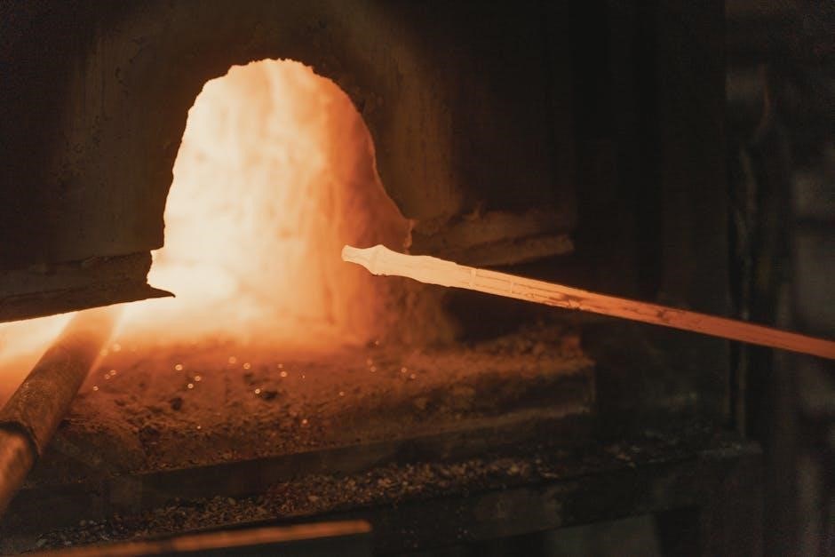
Understanding a gas furnace’s operation begins with recognizing the intricate sequence of events, often detailed in comprehensive PDF documentation. These documents, frequently provided by manufacturers, outline the precise steps from the thermostat’s initial call for heat to the final shutdown. The sequence involves activation of the induced draft motor, gas valve opening, pilot ignition, and main burner ignition—all governed by safety interlocks.
Accessing these PDF guides is paramount for technicians and homeowners alike, offering insights into troubleshooting and maintenance. They illustrate the interplay between electrical and mechanical components, ensuring efficient and safe heating. Proper understanding, facilitated by these resources, is key to diagnosing issues and performing necessary upkeep.
Understanding the Core Components
Essential components driving gas furnace operation are meticulously detailed within sequence of operation PDFs. These include the gas valve, responsible for regulating gas flow, and the flame sensor, crucial for safety. The induced draft motor ensures proper venting, while the high-limit switch prevents overheating. PDF documentation often features schematic diagrams, aiding in comprehension of wiring and component interaction.
Furthermore, understanding the function of each part, as outlined in these guides, is vital for effective troubleshooting. Accessing these resources allows for pinpointing malfunctions and performing targeted repairs. Manufacturer-specific PDFs provide detailed component specifications and operational characteristics, enhancing diagnostic capabilities.
Detailed Sequence of Operation Stages
Detailed stages, from thermostat calls to burner ignition, are comprehensively illustrated in sequence of operation PDFs, offering a step-by-step operational guide.
Stage 1: Thermostat Call for Heat
The initial stage, as detailed in numerous gas furnace sequence of operation PDFs, begins with the thermostat detecting a room temperature below the setpoint. This triggers a call for heat, sending a low-voltage signal – typically 24VAC – to the furnace control board. This signal initiates the entire heating process. The control board then verifies the safety interlocks are in place, ensuring conditions are safe for operation.
Crucially, these PDF documents emphasize the importance of a stable power supply and proper thermostat wiring for reliable operation. A clear understanding of this initial signal pathway, often depicted in schematic diagrams within the PDFs, is fundamental for troubleshooting heating issues. The control board’s response to this call is the foundation for all subsequent stages.
Stage 2: Induced Draft Motor Activation
Following the thermostat’s call for heat, the furnace control board, as outlined in gas furnace sequence of operation PDFs, activates the induced draft (ID) motor. This motor’s primary function is to exhaust flue gases from the heat exchanger and combustion chamber, creating a negative pressure environment. This negative pressure is vital for safe and efficient combustion.
Detailed wiring diagrams within these PDFs illustrate the ID motor’s electrical connection to the control board. Proper ID motor operation is confirmed by pressure switches, which verify adequate draft before proceeding. Troubleshooting guides in the PDFs often pinpoint ID motor failures or pressure switch malfunctions as common causes of no-heat situations. This stage is critical for preventing carbon monoxide buildup.
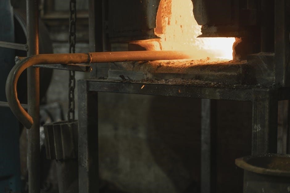
Stage 3: Gas Valve Opening & Pilot Ignition
Once the induced draft is established and verified, the furnace control board, as detailed in gas furnace sequence of operation PDFs, energizes the gas valve. This allows gas to flow to the pilot assembly. Simultaneously, the control board initiates the pilot ignition sequence, typically using a spark igniter or a hot surface igniter.
Manufacturer-specific PDFs provide schematics illustrating the gas valve’s wiring and operation. Successful pilot ignition is confirmed by the flame sensor (discussed later). Troubleshooting sections within these documents often address issues like a faulty gas valve, a defective igniter, or insufficient gas pressure. Understanding this stage, via the PDF, is crucial for safe furnace operation.
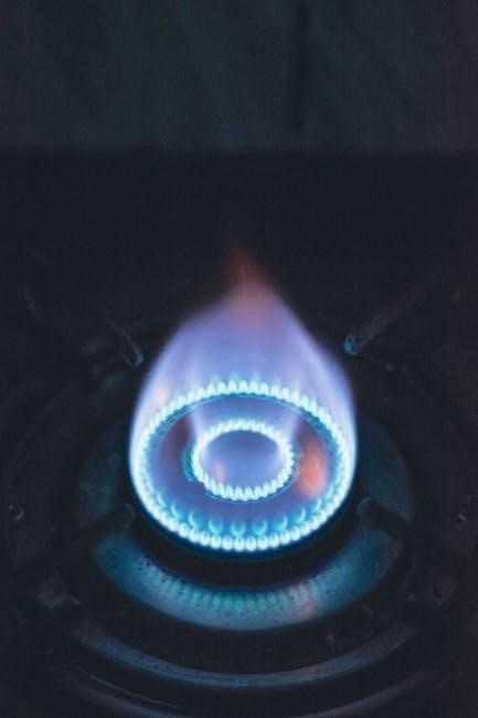
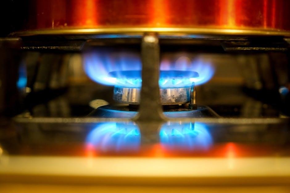
Stage 4: Main Burner Ignition & Flame Sensing
With a stable pilot flame confirmed, the furnace control board, as outlined in gas furnace sequence of operation PDFs, opens the main gas valve fully, allowing gas to flow to the main burners. This ignites the burners, producing substantial heat. Crucially, the flame sensor continuously monitors for the presence of a flame on the burners.
Detailed PDF documentation from manufacturers illustrates the flame sensor’s location and operation. If the flame sensor doesn’t detect a flame within a specified timeframe, the gas supply is immediately shut off as a safety measure. Troubleshooting guides within these PDFs address common issues like a dirty flame sensor or a weak flame signal, ensuring safe and efficient furnace operation.
Safety Mechanisms & Interlocks
Gas furnace sequence of operation PDFs detail critical safety features, including high-limit switches and flame sensors, preventing hazardous conditions during operation.
High-Limit Switch Functionality
Detailed in gas furnace sequence of operation PDF documentation, the high-limit switch is a vital safety component. It’s designed to terminate furnace operation if excessive temperatures are detected within the heat exchanger. This prevents overheating, a potentially dangerous situation that could lead to component failure or even a fire.
The switch typically cycles on and off, interrupting power to the gas valve and induced draft motor. Understanding its precise location and operation, as outlined in the PDF, is crucial for troubleshooting overheating issues. Regular inspection, as part of annual maintenance, ensures proper functionality and reliable safety protection. Failure to address a faulty high-limit switch can compromise the entire heating system’s safety.
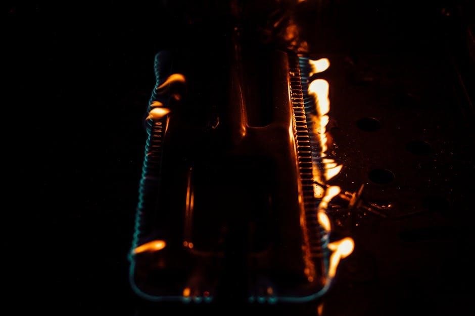
Flame Sensor Operation & Troubleshooting
Gas furnace sequence of operation PDF guides detail the flame sensor’s critical role in verifying a stable flame. This sensor, typically a metal rod positioned near the burner, detects the presence of ionization current created by the flame. If no flame is detected, the gas valve shuts off, preventing unburned gas from accumulating – a significant safety feature.
Troubleshooting often involves cleaning the sensor with fine steel wool to remove carbon buildup, which can impede its function. PDF documentation outlines testing procedures using a multimeter to confirm proper grounding. A faulty flame sensor is a common cause of furnace shutdowns, and understanding its operation, as described in the manual, is key to efficient repair.
Gas Valve Safety Shut-Off Procedures
Gas furnace sequence of operation PDFs emphasize the gas valve’s vital safety role. These documents detail multiple shut-off triggers, including flame sensor failure, high-limit switch activation, and pressure irregularities. Upon detecting a problem, the valve immediately ceases gas flow to the burner, preventing hazardous gas buildup.
Manual shut-off procedures, outlined in the PDF, are crucial for maintenance and emergencies. Technicians must verify complete gas shut-off before servicing any furnace components. The documentation also details procedures for resetting the valve after a safety lockout, often requiring a manual reset button. Understanding these procedures, as detailed in the manual, is paramount for safe operation.

Electrical System & Wiring Diagrams
Schematic diagrams, often found within a gas furnace sequence of operation PDF, are essential for troubleshooting and verifying correct wiring configurations.
Schematic Diagram Interpretation
Understanding gas furnace wiring diagrams, frequently included in a comprehensive sequence of operation PDF, requires a systematic approach. Begin by identifying key components – the gas valve, induced draft motor, flame sensor, and control board – represented by standardized symbols. Trace the power flow from the electrical supply, noting safety interlocks like the high-limit switch and flame sensor, which dictate operational sequences.
Pay close attention to wire colors and labeling, as these indicate specific functions. A PDF document will often include a legend clarifying these symbols and color codes. Familiarize yourself with the control board’s terminals and their corresponding functions. Correct interpretation is vital for accurate troubleshooting and safe maintenance, ensuring the furnace operates efficiently and reliably. Diagrams like TUY060,080,100,120R9V-V are examples.
Wiring Considerations for Gas Furnaces
Gas furnace wiring, detailed within a sequence of operation PDF, demands strict adherence to electrical codes and manufacturer specifications. Proper grounding is paramount for safety, preventing electrical shock and ensuring reliable operation. Wire gauge must match the amperage requirements of each component, preventing overheating and potential fire hazards.
Connections should be secure and insulated, utilizing appropriate connectors and wire nuts. When referencing a PDF, note any specific wiring configurations for the gas valve, induced draft motor, and control board. Always de-energize the furnace before performing any wiring work. Careful attention to these details, alongside the schematic diagram, guarantees a safe and functional heating system.

Troubleshooting Common Issues
Diagnostic steps, outlined in a gas furnace sequence of operation PDF, help pinpoint issues like no heat or pilot light failures for effective repairs.
No Heat – Diagnostic Steps
When facing a “no heat” situation, consulting a gas furnace sequence of operation PDF is paramount. Begin by verifying the thermostat call for heat, ensuring proper settings and battery function. Next, check the induced draft motor; its activation is a critical early stage.

Inspect the gas valve for proper operation and confirm pilot ignition. Utilize the PDF’s schematic diagrams to trace electrical circuits, focusing on the flame sensor and high-limit switch. A malfunctioning flame sensor will shut down the system.
Review safety shut-off procedures detailed in the documentation. If issues persist, carefully examine wiring connections and consider potential gas supply problems, always prioritizing safety.
Pilot Light Issues & Solutions
Troubleshooting pilot light problems requires referencing the gas furnace sequence of operation PDF for your specific model. A consistently extinguished pilot suggests a dirty pilot orifice, a faulty thermocouple, or insufficient gas pressure. Consult the PDF’s diagrams to locate these components.
Cleaning the pilot orifice carefully is often the first step. If the thermocouple is defective, replace it following the instructions in the documentation. Low gas pressure requires professional attention; never attempt to adjust the gas valve yourself.
Always prioritize safety. The PDF outlines proper shut-off procedures before any maintenance. Verify proper venting and gas leak detection after any repairs.
Maintenance & Best Practices
Regular filter replacement and annual furnace inspections, guided by the sequence of operation PDF, ensure optimal performance and longevity of the system.
Regular Filter Replacement
Maintaining a clean air filter is paramount for efficient gas furnace operation, directly impacting airflow and overall system performance. Referencing the furnace sequence of operation PDF can highlight the filter’s location and recommended replacement frequency. A clogged filter restricts airflow, forcing the furnace to work harder, increasing energy consumption, and potentially leading to overheating.
Regular checks – monthly during peak seasons – are advisable; Different filter types (disposable, washable, electrostatic) have varying lifespans. The PDF documentation often specifies the correct filter size and MERV rating for your specific model. Ignoring filter maintenance can void warranties and contribute to premature component failure, necessitating costly repairs. Prioritize filter replacement as a simple yet vital maintenance task.
Annual Furnace Inspection Checklist
A comprehensive annual inspection, guided by the gas furnace sequence of operation PDF, ensures optimal safety and efficiency. Begin by visually inspecting the burner for corrosion or damage. Check the flue pipe for proper venting and any obstructions. Verify the functionality of safety controls, including the high-limit switch and flame sensor, as detailed in the documentation.
Furthermore, examine electrical connections for tightness and signs of wear. Test the gas valve for leaks using a suitable solution. Review the blower motor and fan for proper operation. The PDF often includes a schematic diagram for troubleshooting electrical issues. Document all findings and address any concerns promptly to prevent potential hazards and maintain peak performance.

Advanced Topics & Considerations
Mathematical modeling of furnace thermal regimes, utilizing resources like the gas furnace sequence of operation PDF, aids in design and optimization efforts.
Mathematical Modeling of Furnace Thermal Regimes
Employing mathematical models to simulate furnace behavior is a complex undertaking, often relying on detailed operational data. Accessing a gas furnace sequence of operation PDF provides essential insights into the system’s dynamic processes. These models, frequently utilizing equations like Peng-Robinson for real gas properties, help predict thermal distribution and efficiency.
However, challenges arise when modeling near critical points where property changes become drastic. Accurate representation of combustion, heat transfer, and fluid flow requires sophisticated algorithms. Ladle furnace thermal regimes, for example, benefit from bubble melt blowing models. Such simulations aid in optimizing fuel consumption, minimizing emissions, and ensuring stable operation, all informed by the procedural details within the sequence of operation documentation.
Real Gas Model Applications in Furnace Design
Utilizing real gas models, like the cubic Peng-Robinson equation, is vital in modern furnace design, particularly when dealing with natural gas combustion. A gas furnace sequence of operation PDF details the precise gas flow and ignition sequences, crucial input for these models. These applications accurately predict thermodynamic properties, especially under supercritical conditions, though challenges exist near critical points due to rapid property fluctuations.
Designers leverage these models to optimize burner performance, enhance heat transfer efficiency, and minimize pollutant formation. Understanding the furnace’s operational sequence – as outlined in the documentation – allows for precise boundary condition setting within the simulation. This ensures the model accurately reflects real-world performance, leading to more efficient and reliable furnace systems.
Resources & Documentation
Locating gas furnace sequence of operation PDFs and manufacturer-specific documentation provides essential insights into electrical and mechanical operational procedures for troubleshooting.
Accessing Furnace Sequence of Operation PDFs
Obtaining detailed gas furnace sequence of operation PDFs is a vital step for technicians and homeowners alike. These documents, often available directly from furnace manufacturers, outline the precise electrical and mechanical steps governing the unit’s operation. Online searches utilizing the furnace’s model number alongside “sequence of operation PDF” frequently yield results.
Furthermore, industry websites and forums dedicated to HVAC professionals often host collections of these manuals. Careful review of these PDFs is essential for accurate diagnostics, safe maintenance, and effective troubleshooting. Understanding the interplay between components – from the thermostat call for heat to the gas valve shut-off procedures – relies heavily on these readily available resources. Always prioritize manufacturer-provided documentation for the most accurate information.
Manufacturer-Specific Documentation
Accessing manufacturer-specific documentation for your gas furnace is paramount for a complete understanding of its sequence of operation. These resources, often available as PDFs on the manufacturer’s website, provide detailed schematics, wiring diagrams (like those for TUY060,080,100,120R9V-V models), and component-level explanations.
Unlike generic guides, these documents reflect the unique design and safety features of your specific furnace model. They detail start-up procedures, troubleshooting steps, and maintenance checklists. Referencing this documentation ensures accurate diagnostics and repairs, avoiding potential hazards. Always prioritize the manufacturer’s instructions when working with gas appliances, as variations exist between brands and models.
